

Low Cost Rocket Launcher Plans
Ultra Low Cost Individualized Rocket Ground Support
Equipment for Classroom Use.
NARAM 42 R&D report by Ted Mahler NAR # 18184 C Division
For our hobby to grow and prosper, young people need to be introduced to joy of rocketry. One of the best ways to do this is to incorporate rocketry in schools. For 8 years I have been a volunteer teacher for a 4th grade, school sponsored, rocket class. One of my goals with this class was to leave each child with, not only the knowledge to continue the hobby, but all the equipment needed as well, including a launch pad and controller. When I was setting up the course I discovered there were few information sources for plans of individual ground support equipment. For this launch equipment I was seeking the following characteristics:
- Low Cost. This was being taught in a small town school where many of the students could not afford a large fee. My goal was $12.00 total to cover the cost of a rocket kit, 3 engines, a launch pad and controller. With $5.00 allocated for the rocket, and $3.00 for the engines, that left only $4 for ground support equipment. Ouch!
- Would require assembly. Nothing teaches better that hands-on experience. I wanted to present some basic electrical theory and having the students actually, build the launch controller would reinforce the theory.
- Assembly must be easy for a 4th grader in a classroom environment where each child may not receive individual attention.
- Equipment should be rugged. These are 4th graders, need I say more?
- Equipment must be able to be easily produced in my garage, for 50 students.
To tackle the cost problem I soon learned that the use of prefabricated parts like pushbuttons quickly ate up the money. Yet not using prefabricated parts increased the time it took me to make the parts. So a compromise had to be reached.
Launch Pad
For the launch pad, bulk, easily available wood was chosen. First a lunch pad base was designed from a 2X4 with legs from 1X2’s. Both easy to find and both cheap. A classic three leg design was chosen for ease of use by the students. A tilting option was built in to the design yet no complicated mechanisms were used.
Construction consists of a triangle base, cut from a 2X4. Using a table saw set to 30 degrees. An angle cut is made on the end of the board. After which the board is turned over and another angle cut is made which produces a wooded triangle.
This method is repeated until enough bases are cut. There is extremely little waste and the cutting is easy and fast.
![]()
Figure 1. Here is the cutting pattern for the pad bases. Each cut is made 30 degrees from the vertical. Remember to flip the board over after each cut.
To complete the base construction, 7/16 inch holes are drilled in the center of each side. Absolute center is not needed. A block of wood with a matching V notch to hold the triangle base speeds up the operation.
Figure 2. Side view of the launch pad base showing the 7/16 hole. Drill a hole in each side. Centering the hole by eye is adequate. A drill press helps!
One last hole is needed. This hole is 1/8 inch hole drilled most, but not all the way through the block in the center of the triangle shaped top.
Now for the legs. They are simple 11 inch cuts from a 6, 8, or 10 foot length of 1X2, sometimes called furring strips. Each pad will need three. After they are cut, drill a ¼ inch hold in the middle of the wide side about ¾ inch from one end.
![]()
Figure 3. One of the three legs required for each launch pad showing the location of the ¼ inch hole.
That’s all the construction you need to do. Now some premade parts. Each pad will need 3 "hanger Bolts" These are special bolts with screw threads on one end and machine threads on the other. Ask for ¼ 20 hanger bolts, 2 inches long. Here the "20" refers to threads per inch. You also need three wing nuts size ¼ 20 for each pad. Don’t buy these at your local hardware store, they usually charge too much. Look in the phone book for a fastener company like Fastenal. Most towns have a place like this and they sell fasteners in bulk much cheaper than the normal retail outlets. Also you will need a launch rod. For these, visit a wielding supply store and ask for 1/8 rods 36 inches long. Tell them what you are doing and most of the time they will sell you rods at cost. Wielding rods are sold by the pound and 5 pounds will contain about 40 to 50 rods. Also, you need old tin can lids with a 1/8 inch hole drilled in the middle. I have a special can opener (made by KRUMPS) which actually peals back the edge of the lid instead of cutting it. This leaves no sharp edges. If you are going to be making a lot of pads, this can opener is well worth the cost and will pay for itself quickly.
 You should assemble one ahead of time just to be sure it all fits but let the students each assemble their own pad. Here is the method and order. Have each student thread the wing nuts onto the hanger bolts. It will only go on one end. I always tell them to put it on the end that is NOT pointy. They usually gets them to the machine thread end quickly. After all are threaded, use the wings nuts as handles and twist the other end of the hanger bolt into the holes drilled in the side of the base block. They need to do this for each of the three bolts. Then using one of the legs as a kind of hammer, they need to tap the wing nuts, in the opposite direction they inserted them, to loosen them yet leaving the hanger bolts in place. After they are loose, the wings nuts can be removed leaving only the hanger bolt in the block. Now place the legs onto the base block by putting the hole in the leg over the hanger bolt. Then rethread the wing nut to hold the leg in place. After all three legs are done. The launch rod is pushed into the 1/8 hole on top of the block. To complete the
pad the tin can lid blast deflector is slid down over the launch rod. It’s that easy. In use, the legs and be adjusted to tilt the pad for wind conditions. So how did we do on cost? Based on making about 40 to 50 pads and assuming you will get 8 legs from an 8 foot 1X2 and about 30 pad bases from a 8 foot 2X4 the cost works out to:
- 1 36 inch wielding rod $0.30
- 3 hanger bolts $0.30
- 3 wing nuts $0.27
- 1 wood base $0.03
- 3 1x2 legs $0.15
- "Blast deflector" $ 0.00
$ 1.05 each!
Not too bad. So can you take $1.05 and go buy these materials for 1 pad? No, of course not. However buying in bulk and doing the cutting yourself brings the cost way down. Students get an inexpensive pad and the pride of assembly with this design. Most of the students paint their pad, which further personalizes it.
The electric launch controller.
Can the same low cost principle apply to making an electric launch controller complete with safety key and continuity light? Absolutely!
Let’s start with the base of the controller onto which everything else is attached. This turns out to be a simple piece of 1X4 wood 6 inches long. I have used pine 1X4, particle board cut to the same size, or any scrap wood. It all will work and there is plenty of scrap wood around. But even if you buy it all the cost will amaze you. Figure 5 is a dimensioned drawing of the base and the holes you need to predrill for the students. Ask a friend who does woodworking about a simple jig to help drill the holes. I made one from scrap wood that allows me to drill each hole, one at a time, in all the bases I have cut. After I have cut that hole in all the bases I reposition the jig for the next hole. It really goes pretty quick.
Next you will need speaker wire. Although I have bought this at Radio Shack, I find that, like buying fasteners at a Fastener Company, there are better places to purchase wire. I go to an electronics distributor or wholesaler. Look in the phone book. Once again tell them what you are doing with the wire. You will need 15 feet of 18 gauge wire per student. I bought my wire in a 1000 foot reel for $50. That is enough for 66 students which makes the wire cost about 75 cents per controller. You will also need the following materials that I order from Mouser Electronics (www.mouser.com)
- 13AC120 test clips (micro clips for the igniter) 2 for each controller.
- 12BH348 4XAA battery holder 1 for each controller.
- 604-L934SGC LED 1 for each controller.
This I do buy from Radio shack.
- 300 ohm resistor (radio shack) 1 for each controller.
From an office supply store:
- A 1 inch bulldog clip (used to slip paper together)
These following items can be found at any building supply store. Buy the nuts, bolts, and screws in boxes of 100.
- 6/32 by 1 ½ inch machine screw 2 per controller
- 6/32 nuts 2 per controller
- #6 X ½ inch sheet metal screws.
- One roll (about 3 feet) of aluminum flashing. It is used for roofing repairs.
Cut the speaker wire into 15 foot lengths. Strip and tin (ask an electronics buddy for help if you don’t understand this) about ¾ inch of the wires on one end and solder the micro clips to the two leads on the other end of the wire.
Solder the led and resistor together and form them into a "C" shape. With one lead of the LED forming the top of the C and one lead of the resistor forming the bottom of the C. Ends of the C should be about 1 and ¼ inch apart. I also put a curl in the ends of the leads to help them fit around the screws that will hold them down. See figure 6 for a better idea of what this looks like. Note that the LED will only work if it is put in correctly. I make up one set and try it out first If it does not work I reverse the LED in my second attempt. Notice that one leg of the LED is longer that the other. Once you figure out which way it should go, use this to help make all the LED/Resistor assembles correct.
 Cut the flashing into 1 inch wide strips and cut the strips into 3 inch lengths. Now fold ½ inch of one end over onto itself to form a double thick end. About ½ inch from the other end put a bend in the metal to make this switch stand up from the wood when it is attached. Also drill a 1/8 inch hole on the left side of the switch about ¼ inch from the side. It is far easier to just look at the picture in figure 5 then to try to make sense of
this written description. Dimensions of the switch are not critical and I find it works best just to make a few and work out the best size.
Assembly order of the launch controller is not critical and since the design is so simple the photographs in figures 6 and 7 will tell you just about all you need to know about where the parts go.
It is best to start by hot gluing the battery holder into the upper left corner of the base. Using the tinned end of the speaker wire thread the 15 foot length of wire down into the large ¼ inch hold close to the top of the base and then up through the other large ¼ inch hole. Push the machine screws up through the bottom of the base and use the nuts to hold them in place. Once again follow the picture to determine the hookup.
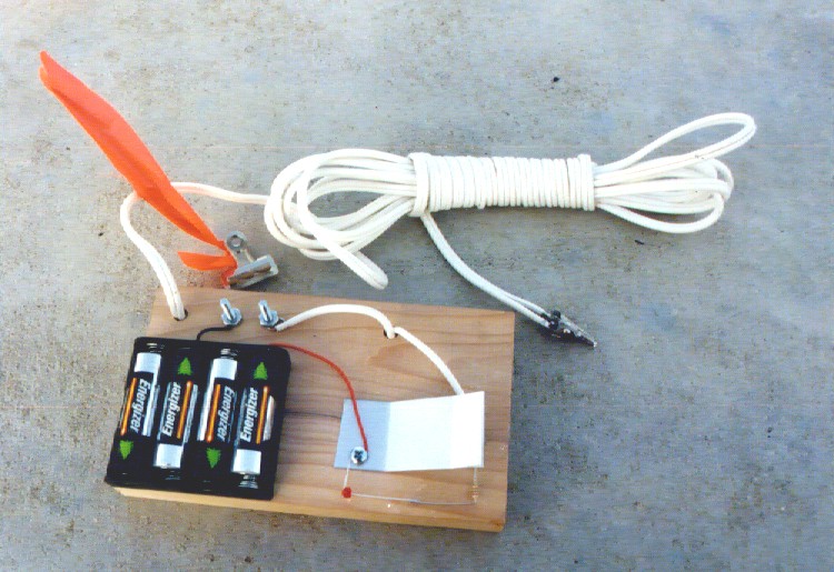
Once complete the controller is used by inserting 4 AA batteries according to the diagram on the battery holder. To arm the controller after the rocket is connected, clip the bulldog clip to the top of the machine screws. This completes the circuit and, if the igniter is hooked up correctly, will light the LED. Pressing the switch will complete the circuit and send the student’s rocket skyward. Cost? Let’s have a look.
Wood Base $0.20
15 feet of wire $0.75
Battery holder $0.65
Micro Clips (2) $0.32
Led $0.17
Resistor $0.05
Bulldog Clip $0.28
Nuts, bolts, screws, $0.20
Aluminum for switch $0.06
$2.85
That just where we needed it! Remembering the cost of the launch pad was about $1.00 you can see that both a launch pad and controller can be built for just under $4.00!
This opens the door for each student to build their very own launch equipment that can be used for a wide variety of rockets. Having the ability and equipment to launch their rockets will allow them to be able to fly whenever it is convenient for them and their family. This allows them schedule more flying days with their friends and that helps their interest and level of fun grow and that helps them become the future of our hobby.