Building Rockets Preview of Member Guidebook
Welcome to this preview of the NAR Member Guidebook, which you’ll receive in hard copy for Joining the NAR!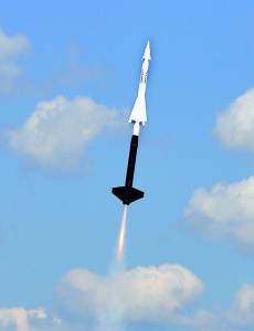
Rocketry Basics
Rocket Anatomy 101
By Mark Newton
Most rockets are composed of sections or parts, carefully chosen and arranged to create a flight-worthy vessel. Understanding the name and purpose of each part is one of the first steps into the hobby of model rocketry. Let’s examine these and how they contribute to the flight of a rocket.
Nose Cone
The nose cone is usually the part that first interacts with the air in flight. The nose cone parts the air as the rocket moves through the atmosphere. Pushing the air out of the rocket’s way creates friction. The friction pushes the nose cone downward, transferring the air’s force to the airframe. The rocket’s passage through the air creates heat of friction; for most model rockets, this heat is trivial, because it lasts only for a few seconds. However, for a slender high-powered rocket that flies several miles high at twice the speed of sound, the heat of friction can melt the paint off the nose cone.
Nose cones come in many shapes: rounded, elliptical, parabolic, ogive, and conical, to name a few. The nose cone usually has a shoulder a section that fits inside the airframe to keep it centered on the rocket and a place on the bottom where the recovery system can be attached. This attachment varies in size with the rocket: model rockets have a plastic slot or small screw eye, while mid-sized rockets often have eyebolts, and large rockets have massive U-bolts or welded eyebolts. Once the recovery system has been attached, the nose cone stays joined to the rocket throughout the flight.
Nose cones are made from many different materials as well: small ones are often molded plastic or wood (balsa wood, basswood); high power manufacturers frequently use fiberglass, carbon fiber, or other composite materials. Composite provide greater strength and less weight, but cost more to purchase. Some people make their own nose cones from wood turned in a drill chuck or wood lathe. Frequently, nose cones on large home-built rockets are constructed by stacking and gluing sheets of foam, shaping the stack with a hot wire cutter, then covering the foam with a fiberglass/carbon fiber skin. The variations are endless.
Airframe
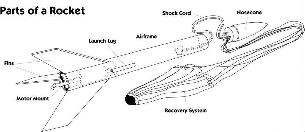
Sometimes called the body tube, the airframe provides the main structure of the rocket, supporting the nose cone and fins. During flight, the airframe is compressed from two directions: the motor pushes up from the bottom during thrust, and the nose cone pushes down as it parts the air. If the rocket veers to one side during flight, the airframe can be hit with air resistance from the side as well. The airframe must be able to withstand these forces, or the rocket will buckle or break. On the inside, the airframe holds the recovery system — the parachute, streamer, etc — as well as other parts, such as centering rings or motor tubes, some of which can also strengthen the airframe.
Rolled paper tubes are the most common form of airframe. They are relatively lightweight, and they crush during a crash to absorb the impact force — a desirable safety characteristic. In high power rocketry, airframes shift to heavy-walled paper, phenolic tubing (paper soaked in a high-temperature phenolic resin), plastic tubing, fiberglass, carbon fiber and other materials. These advanced materials handle the greater forces imposed by high-thrust motors and greater weights. Some builders reinforce their airframes by covering them with epoxy and fiberglass or other materials. For scratch-built rockets, paper tubes of all sizes, from paper towel rolls to oatmeal containers to concrete forming tubes, have been employed as airframes. Most airframe tubes can be purchased in lengths of 2-5 feet. When longer airframes are needed, a coupler is placed between two tubes to join them into one long tube. The coupler is usually made of the same material as the airframe. No matter the material, the goal is to create a structure that will not fold under the stresses of flight.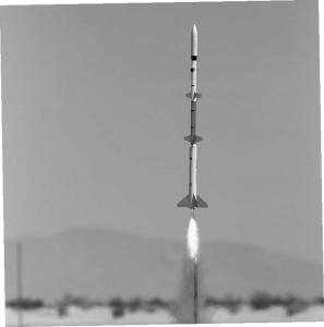
Fins
Fins provide the rocket’s guidance. In flight, air flows over the fins, beginning at the leading edges and ending at the trailing edges. When a rocket is flying in a straight path, it encounters less air resistance (drag) than if it flies at an angle. If the rocket attempts to turn, the fins opposite the direction of turning are moved into the airflow, and the air pushes more on the exposed fin surfaces than on the other fins, until the rocket rights itself, just as a weather vane always points into the wind. Fins are usually the first part of a rocket to fail during powered flight, because they have air flowing around them on every side, and they are made of thin material to reduce their air resistance and weight. Fins can fail because they literally flutter apart, or can simply separate from the rocket because they are not properly attached. In either case, failure of one fin usually dooms the flight, as its guidance system is now unbalanced, and there is less air resistance near the tail once the fin is gone, moving the center of pressure (CP) forward, perhaps even ahead of the center of gravity (CG). At this point, the rocket often does a few quick loops to celebrate the loss, likely tearing the airframe apart in the process.
Because thin fins have less air resistance than thick ones, rigid materials are used to provide stiffness with minimum thickness. For model rockets, balsa wood or basswood are favorites. Competition models may use waferglass, a thin material made from plastics and fiberglass called G-10 (garolite). High power rockets use aircraft-grade birch plywood or thicker sheets of G-10. These materials are strong, but they become very heavy as their size and thickness increases. To reduce the weight of large fins, some builders use lighter materials for the center (core) such as foam or balsa wood, add hardwood strips for the fin edges, then reinforce the core with a skin of thin hardwood or composites, such as fiberglass/epoxy. If built properly, these reinforced fins can perform as well as solid fins, but with a fraction of the weight.
Whatever material is chosen, the fins must be secured to the rocket at their root edges, so they will not separate from the airframe during the most stressful part of the flight (usually at motor burnout), sometimes at speeds beyond 1000 miles per hour. Model rocket fins are usually just glued to the airframe surface, while high power rockets often have fins with tabs that fit through slots cut in the airframe; the tabs are glued to the motor tube. These are known as through-the-wall fins; they gain strength by being glued both to the motor tube and to the airframe. There are many other techniques to strengthen fin attachment that you will find as you progress in the hobby. No matter the technique, the goal is to keep the fins attached to the rocket throughout the flight.
Motor Tube
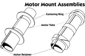 The motor tube contains the motor and is attached to the airframe in some manner, usually with centering rings. The motor tube is often made of the same material as the airframe. A model-rocket motor tube often has a thrust ring inside and the motor pushes against the ring during thrust. High power rockets have no thrust ring inside — the thrust ring is at the aft end of the motor. This lets you insert motors of different lengths without spacers. The motor tube transfers the thrust of the motor to the centering rings, which transfer it to the airframe. Therefore, the motor tube and centering rings must be able to withstand the highest impulse produced by the motor. In addition, the motor tube must be able to handle the heat produced by the motor, where surface temperatures can go beyond 200F.
Centering Rings
The centering rings center the motor tube inside the airframe and transfer the thrust of the motor to the airframe. Model-rocket centering rings are made of cardboard or balsa wood. For high power rockets, aircraft-grade plywood or G-10 is the material of choice. A rocket weighing up to 3 pound would probably have 1/8″-thick plywood centering rings; a 30-pound rocket might use 3/4″ plywood. Just like fins, centering rings get very heavy as they get larger and thicker. As with fins, centering rings can be made from lighter materials, reinforced with composites like epoxy/fiberglass to give the same strength as wood but with less weight.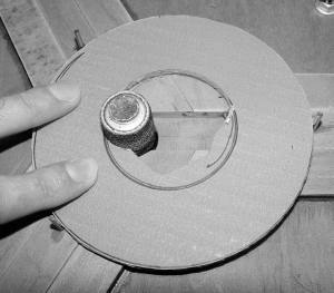
In larger rockets, it is common for the forward centering ring to do double duty: a U-bolt or forged eyebolt in the centering ring provides a solid attachment point for the recovery system. Likewise, the aft centering ring often holds the motor-retention hardware.
Motor Retention
Once a model-rocket motor’s propellant has burned out, its delay charge gives the rocket time to coast to maximum altitude. Once this delay burns through, the charge pressurizes the interior of the rocket, forcing it apart and deploying the recovery system; however, when the interior is pressurized, the rocket motor will be blown out the aft end of the rocket unless something restrains it. The motor-retention system secures the motor, so it cannot leave the motor tube in flight. An engine holder, a lightweight metal clip, is frequently used for small motors. The clip snaps over the motor to restrain it, then the clip can be pulled back to release the burned-out motor. This style of clip is found in most kits in the hobby shop.
Such a clip is inadequate for high power rocket motors: most large rocket kits do not include motor retention, allowing the builder to choose a suitable method. As a result, other retention devices have been developed for larger motors. A common homemade design is the “Kaplow clip”, in which a bolt is threaded into a blind T-nut set in the centering ring. The bolt and T-nut secure a metal tab that hooks over the aft ring of the motor. Several commercial retainers are available, including variations of the Kaplow clip (e.g. PML), retainers with snap rings (e.g. Giant Leap Rocketry) and threaded retainers (e.g. Aeropack). All these devices have different benefits and costs, but all accomplish the primary job: keep the motor in the rocket.
Recovery System
The recovery system consists of several parts that work together to reduce the airspeed of the rocket, so it can be recovered and flown again. The NAR safety code requires every rocket to have a recovery system. A typical recovery system consists of shock-cord attachment point(s), a length of shock cord, flame protection, and the recovery device itself, which is usually a parachute.
If everything goes perfectly, the recovery system is deployed precisely at apogee, the peak of flight, when the rocket is moving very slowly. Things do not always happen perfectly. If the recovery system is deployed a few seconds before (or after) apogee, the rocket may be moving upward (or downward) at high speed. Ejecting a parachute, while moving at 300 feet per second(fps), puts a great strain on the chute, the shock cord, the attachment points, and the airframe itself. Recovery systems must be able to handle forces 40-60 times the rocket’s total weight. Model rockets are relatively lightweight, so a folded-over piece of paper, glued to the shock cord and to the inside of the airframe, is adequate. Some models use a piece of Kevlar around the motor tube for the attachment point.
However, the attachment point must be much stronger for bigger, heavier rockets. Large rockets use one or more U-bolts or forged eyebolts through the centering rings to absorb the large stresses of deploying the recovery system. Large rockets may also use a Nomex deployment bag or some similar technique to delay the opening of the parachute. A delayed opening has advantages: when the rocket deploys its recovery system, it separates into pieces connected by the shock cord, usually (a) the nose cone, (b) the chute, and (c) the airframe, motor, and fins. While the assembled rocket is highly streamlined, so that it can move through the air with minimal drag, its individual components are not. Once the nose cone and airframe separate, the increased drag will quickly slow down the rocket, even before the parachute opens. Delaying the parachute opening for a second or two can mean the difference between opening at 300 fps or 100 fps — a large difference in stress on the recovery system.
Rockets can be recovered by many techniques, including parachute, streamer, glider, helicopter, featherweight, tumble, and nose blow for starters. The most common recovery method is the parachute or streamer for model rockets, with parachutes being the rule for high power rockets. Parachutes also change as rockets change, from inexpensive plastic sheets in model rockets to the more expensive, bulkier, and heavier nylon fabric for large rockets. Plastic parachutes, even well constructed ones, cannot handle the stresses imposed by large, heavy rockets. Streamers work well for small rockets, but are not effective for safe recovery of heavy rockets.
Commercial motors typically use black powder (BP) to pressurize and separate the rocket for recovery. BP burns at temperatures near 2000F, which can destroy nylon or plastic. To protect heat-sensitive rocket parts, flameproof wadding is placed between the motor and the recovery system. As rockets get larger, the wadding may be replaced with a cloth made of flameproof aramid fibers, such as Kevlar or Nomex. Another approach is to cool ejection gas before it contacts the sensitive parts, by making the gas pass through a series of offset baffles or a mass of heat-resistant material such as coarse stainless steel wool.
Launch Lug/Rail Buttons
The launch lug is a small but important part of the model rocket. The lug fits over the launch rod, so that the rocket is guided along the rod for the first few feet of flight, while it is still moving too slowly to be stabilized by fins. The launch rod may be 1/8″ in diameter for small model rockets, up to 1″ for large rockets. It is important to select a rod that is proper for the weight and length of the rocket: a 1/8″ rod works fine for small rockets, but it is inadequate for, say, a 1-pound rocket, where a 1/4″ rod is a better choice. Most flyers use a rod between 3 and 6 feet long. One disadvantage of a launch rod is “rod whip”: as the rocket leaves, the rod whips, sometimes throwing the rocket off its flight path.
Since rails are stiffer than rods, they are a good choice for high power rockets. Rail buttons or guides are then used on the rocket instead of lugs. Seen from the top, a rail appears like the letter C. The button or guide slides down the gap in the rail. The rocket moves up the gap during flight. A rail can be reinforced with guy wires, and it can handle large rockets without rod whip. In spite of the greater cost of rails, they are increasing in popularity. Launch buttons and rail guides differ only slightly: a button looks like a miniature sewing spool, while a guide is a longer piece with a slot on each side, to fit down the rail.
Yes, it is the always the first rule in construction: read and follow the directions. But now you want to build a rocket using your own parts, or you want to modify a manufacturer’s kit for more radical flights. What can you do to keep it together with that F motor, when the kit was really designed for a D motor? Simple: use your bag of building tricks to reinforce key parts of the rocket so it can “return alive” from that flight you’ve planned.
The Fundamental Rule of Building
All right, maybe there are more rules than one to remember. But over time this rule keeps moving to the top of the list: MORE ATTACHMENT SURFACE AREA IS BETTER. You will notice how much the surface area impacts the various components when the rocket is assembled, for example, sanding a surface before gluing cuts micro-ridges in the surface. These ridges provide more surface area for the glue to bond to, increasing the strength of the bond. You will build stronger rockets if you do things to increase surface area as you build.
Choose Your Adhesive Wisely
Rocket parts come in a variety of materials: molded plastic, paper, cardboard, plywood, balsa wood/basswood, phenolic tubing, Quantum tubing, fiberglass, and aluminum are some of the materials in your rocket. No single glue has the ideal properties to bond all these materials together. To achieve the greatest strength with the least weight, you must choose adhesives with the best properties for the materials you want to bond. For example, two-part epoxy gives a strong bond to hold wood fins on a paper body tube, but it adds more weight to the rocket than yellow (aliphatic) glue does. For bonding paper and wood products together, yellow glue is your best choice. It is stronger than the materials you will bond. Once glued, the parts will strip away from the glue before the glue itself fails, and yellow glue is much easier to handle than epoxy: no mixing, no gloves, less expense, and water clean-up. Outside of wood and paper, most other materials adhere best with epoxy, including phenolic tubes, G-10 fins, Quantum tubing, plastic nose cones, and aluminum. Epoxy is the rocketeer’s friend when bonding two items made from different materials.
NOTE: You will become hypersensitive (allergic) to epoxy over time if you work with it without wearing protective equipment such as nitrile gloves. Latex gloves do not protect you from epoxy. Also, use epoxy cement only in areas with good ventilation.
Now, having talked up epoxy for most materials, let’s look at the exceptions. When building many of the new ready-to-fly kits, you can use modeling cement to bond plastic to plastic. Also, most epoxies do not hold up under high temperatures. For bonding metal motor mounts or retainers to motor tubes, special high-temperature epoxies are recommended. For field repairs, nothing beats cyanoacrylate (CA), also known as “super glue.” It will repair broken fins and launch lugs. It is wonderful stuff to have in your field box. CA also has another feature: when soaked into paper or wood, it acts like an instant sealer, making the fibers stiff. CA-soaked items sand easily, without the “fuzz” that normally accompanies sanded wood or paper. You have to pick the right CA for the job, as it comes in thin, medium, and thick viscosities. Thin CA is best for soaking into wood/paper, while medium or thick CA is best for bonding materials in construction or field repair. Some rocket manufacturers recommend CA for constructing their kits.
Fins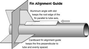
For the typical rocket, fins and motor mounts are the parts that receive the most stress in flight. Motor thrust and wind shear both attempt to shred fins from the airframe. The fins usually also receive a beating when the rocket hits the ground. Reinforcement and building techniques can increase the strength of fins. Let’s discuss some techniques for wringing more performance from your fins:
Reinforce your fin stock. Balsa or plywood fins can be reinforced with a layer of typing paper. Coat the fins on both sides with a thin coat of yellow glue, cover each side with typing paper, then put a layer of wax paper over the typing paper. Press the whole setup under books, bricks, or something else flat and heavy for several hours while the glue dries. After the glue has dried, remove the fins, peel off the wax paper, and carefully coat the typing paper with CA. The CA will stiffen the paper and wood so that it sands easily. From this point, the fin can be sanded, cut, or treated like any other balsa fin. This technique also eliminates the need for sealing balsa fins prior to painting.
Reinforce your fin joints. Increasing the surface area of your fin joint will keep fins attached through those high-performance flights, especially if your fins are attached directly to the airframe (surface mounted). The simplest reinforcement is a glue fillet, which forms a smooth joint between airframe and fin surfaces. Proper fillet technique is discussed in most basic rocket kits. For more strength, use reinforcement materials. Tissue paper and yellow glue work great for model rockets. Cut a rectangle of tissue paper as long as the fin joint to be reinforced, and about two inches in width. Cover the tissue with a thin coat of yellow glue and gently push it into the joint-a Popsicle stick helps. You can increase the strength further with a second layer of tissue. After you’ve done several, you will be able to create a smooth reinforcement that keeps those fins attached. This technique also works for high-power rockets-substitute fiberglass cloth and epoxy as reinforcement materials.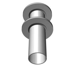
Use through-the-wall (TTW) fins. Through-the-wall fins have tabs that go through the airframe and bond directly to the motor tube. This requires fin slots to be cut through the airframe. TTW fins achieve greater strength by providing multiple locations (that’s surface area) to bond the fins to the airframe and motor tube: fillets can be placed on the inside and outside of the airframe and on the motor tube, especially if the aft centering ring is removed to permit access to the interior of the rocket. To get this access, slide in the motor mount and centering rings, but glue only the forward centering ring to the motor tube—do not put any glue on the aft centering ring. Once the forward ring has dried, carefully remove the aft ring, using a hobby knife. Once the aft ring is removed, you will have access to the TTW fins, and can now put glue fillets or reinforcements on every fin/airframe joint. This makes an incredibly strong fin joint. Once all glue is set, the aft centering ring can be glued into place. Another way to create a TTW setup is to glue centering rings, fins, and recovery attachment to the motor tube, then slide the whole unit into the airframe. This is a great way to build a strong structure, but requires the rocket’s fin slots to extend to the rear of the airframe.
Your choice of technique may be limited by your rocket choice: for example, a kit with surface-mounted fins will eliminate the TTW technique, but you could reinforce the fin and the fin joint. In addition, these techniques can be combined: paper-reinforced balsa fins can be designed for through-the-wall mounting, with tissue paper reinforcements at the joint.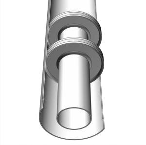
Airframe and Coupler
It is pretty rare to have a rocket fail in flight due to collapse of the airframe if the airframe is commercially available tubing intended for the size motor used. Your chance of failure becomes greater with long, slender rockets such as SuperRoc competition models. To strengthen airframes, two general techniques are reinforcement with composite materials like fiberglass (or carbon fiber) and epoxy, or using a smaller tube inside the airframe-a “tube in a tube” design. The tube in a tube is a simple technique to add considerable strength to the airframe. A set of centering rings keeps the inner tube correctly located inside the airframe. This technique can be even more effective when two-part foam is poured between the two tubes and permitted to harden. Another variation is a ring of wooden strips glued around the inside (or outside) of a tube. You have to be careful about wood choice here: stay with lightweight woods like balsa, basswood, or spruce. Consider a combination: a tube within a tube, centered with a series of balsa wood strips. This can turn a model rocket airframe into a mid-power (or even high power) airframe. If you have enough couplers, gluing them inside the airframe is a simple way to double the airframe’s thickness.
One more trick: the ends of a body tube can be hardened by adding a few drops of thin cyanoacrylate (CA) and giving it several minutes to cure. Once cured, the hardened ends can be sanded to a smooth finish-a great way to permit nose cones and transitions to slide easily on/off the tubing. Do this in a well-ventilated area because of the strong CA fumes.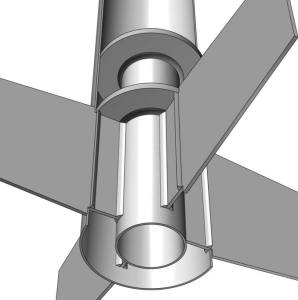
When a long rocket has an airframe failure, it almost always occurs at a coupler joint. As a rule, couplers are made to be the same thickness as the airframe tubing. If your coupler appears to be thin, you might want to strengthen it. Think of a coupler as an airframe, and use the same techniques to stiffen the inner wall of the coupler.
Nose Cone
Really, there is not much you should do to increase the performance of your nose cone. One area that you can improve is the attachment point of the nose cone to the recovery system. Some nose cones provide no attachment point, and some provide a point that is probably too weak. In general, you want an attachment point that is able to handle loads that are fifty times the weight of the nose cone. For example, a 6-ounce nose cone needs an attachment point that can handle loads of 6 ounces x 50 = 300 ounces.
There are several ways to get this type of attachment point. Some nose cones have a spot in their base to permit a quarter-inch eye to be screwed into the base. If an eye is used, always try to use one that does not have any break where the circle closes. Solid eyes, whether welded, cast, or forged, can handle 2–3 times the working load of an open eye, and will not open up under high loads. If your nose cone has no attachment point, then create one: invert the nose cone and pour a small amount of epoxy into the nose tip. Use a stick to push a piece of tubular nylon or Kevlar string into the epoxy, and permit it to cure. Another simple attachment point can be made by placing a piece of Kevlar or tubular nylon under a small square of fiberglass, saturated with epoxy glue. Press the square inside the nose cone, and permit it to cure. The larger the fiberglass square, the less likely that it will be pulled from the nose cone.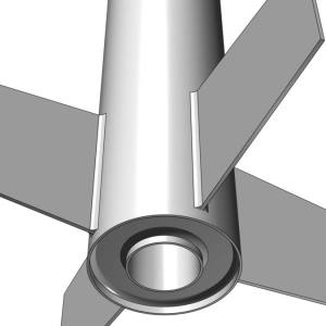
If your nose cone is made of balsa wood, you can seal the nose cone and give it a hard shell by dripping thin cyanoacrylate (CA) over the nose cone. This will harden the wood’s fibers, making it easy to sand. Next, fill in deep groves with Elmer’s Fill-N-Finish Lite, sand again, and you’re ready for final finishing.
Launch Lugs/ Rail Buttons
Among fliers of mid and high-power rockets, there is a move away from launch lugs toward rail buttons/guides. Rails are more rigid than rods, making them a better choice for those long and heavy rockets. Whether you use launch lugs or rail buttons, the biggest concern is always getting a good attachment to the airframe. For launch lugs, it is easier to use paper launch lugs on paper airframes, and brass or aluminum lugs on phenolic, fiberglass, or Quantum tubing. Paper lugs on paper airframes bond firmly if both surfaces are sanded before applying yellow glue. A little more work is required for brass or aluminum launch lugs, as they have a much smoother surface. To prepare metallic lugs, first sand the lug and the airframe with extra-fine sandpaper to increase the bonding surface, then clean both surfaces thoroughly (alcohol is recommended as a cleaning solvent). The surfaces can then be bonded with epoxy or, for more strength, cover the lug with a piece of epoxy-soaked fiberglass, extending over onto the body tube an inch on each side. This increases the bonded surface area, decreasing the chance that the lug will pull off during flight.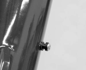
Rail buttons and rail guides vary. Some rail guides are designed for a surface mount, using an adhesive strip. These are simple to attach, but great care has to be given to assure a good fit to the airframe and a clean surface for the adhesive. Before applying the adhesive, lay a piece of sandpaper, rough side up, on the airframe. Slide the rail guide back and forth on the sandpaper, keeping it firmly against the airframe. This sanding will gradually make the base of the guide conform to the curvature of the airframe. Once the sanding is complete, sand the area on the airframe, clean both surfaces, place the adhesive strip on the rail guide, and place the guide on the airframe. It is important that these surface-mounted rails be kept under pressure for several hours. Pressure can be applied with clamps (spring, rope, woodworking clamps, etc.). Traditional rail buttons are not surface mounted-they must be attached through the airframe, and ideally, also through a small piece of wooden reinforcement inside the airframe. An extra piece of wood adds significant strength to the button. It’s a good thing. Retrofitting rail buttons to an existing rocket is more problematic, since you cannot get inside the rocket to get a good attachment point for each button. In this case, think about hanging a picture at home: use drywall anchors. Find a screw that fits the rail button, and buy the matching plastic expansion piece. Drill the hole, insert the plastic expansion piece, then screw the button down on the airframe. This trick also works well for retrofitting motor-retention tabs.
Motor Retention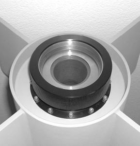
Nothing ruins your day like losing your hundred-dollar reload case and driving your beautiful rocket into the earth because the recovery system did not deploy because the motor casing was ejected. It’s almost enough to make you want to go back to the office-almost. This need not happen to you. A little time and effort spent on motor retention will pay rewards in recovering your rocket to fly again. Most model-rocket kits provide motor retention in the form of a clip, but as you move into larger rockets, you are left to provide your own retention system. In general, retention systems are designed to work with motor casings that have a thrust ring built into the aft end of the motor. A retention system works best when it is built into the rocket during construction. If you are new to retention systems, start with a purchased one. They are available from a number of vendors, such as Aeropack, Public Missiles, Giant Leap Rocketry, Rocketman, Bourne Again Rocketry, to name a few. Once you’ve seen a few homebrew setups and asked some questions, you will be ready to make your own system. For a time-tested design, look at “Kaplow clip” below. There are dozens of designs that all function well. Attend a club launch and just look around-you’ll see for yourself. A personal favorite is a piece of quarter-inch all-thread, attached to the side of the motor tube with a wrap or two of glue-soaked paper and positioned so the threads protrude about half an inch beyond the aft end of the motor tube. On the field, slide in your motor, place a washer and quarter-inch nut on the all-thread, and snug it down: simple, cheap, and effective.
Recovery System
Nowhere does focusing on surface area pay more dividends than in recovery-system construction. An adequate system has to handle about fifty times the rocket’s weight as it slows the rocket to a safe descent rate. The ideal situation is to spread this load out over a large area. Attaching the recovery system in two or three places or bonding the recovery strap down the side of the motor tube or along the edge of two or three through-the-wall fins are some ways to spread that recovery load across the rocket. Many model rocket kits advise you to glue a shock cord in a paper tab, and then attach 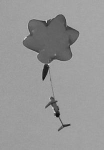 the tab to the airframe sidewall. This technique works well for small, light rockets but generally not on large, heavy ones. Another place to beef up your recovery system is the parachute. You can replace plastic ‘chutes with nylon ones for extended durability; however, you can also strengthen that plastic ’chute for a few pennies. Remove the shroud lines that came with the ’chute, and make your own with upholstery thread from a fabric store. Better yet, cut the thread long enough to go across the center of the parachute canopy and down two opposite sides to form two shroud lines. Tape the thread down to the canopy with a good quality tape, such as 3M. This will produce a parachute that is much tougher and more resistant to shroud-line failure.
Elastic shock cords are a source of contention in rocket circles. Your rocket will be more reliable if you discard the elastic shock cord that comes with the kit and replace it with one that is the same diameter but 4-5 times the length of the rocket. Longer is good, as it provides more shock cord to absorb opening loads. Longer cords also lessen the chance that two separated rocket parts will snap together and hit each other. Elastic is available at fabric stores. In larger rockets, avoid elastic and use to tubular nylon or Kevlar.
For flight prep, abandon the wadding in favor of Nomex cloth available from vendors, or install an ejection baffle system. Although they cost money up front, they simplify your flight prep every time you use them.
Centering Rings
The lowly centering ring is a hidden part that performs an essential duty. At liftoff, your rocket motor pushes against the thrust ring, which pushes against the motor tube, which pushes against the centering rings, which finally pushes the airframe. Centering rings therefore transfer the motor’s thrust to the airframe. In most large rockets, they are also the attachment point for the recovery system. They must be able to withstand more force than your motor can produce. Model rockets typically use cardboard or balsa wood for centering rings, while mid and high-power rockets use plywood, G-10 phenolic, or composite materials for strength. The problem with materials like plywood and phenolic is their weight-a pair of rings can add significant weight to the rocket. You have to challenge yourself to build strength, not weight. For example, a rocket with through-the-wall (TTW) fins needs centering rings mainly just to center the airframe and contain the ejection charge-the fins carry most of the flight stresses, since they are attached to both the motor tube and the airframe. In this situation, the rings could be made of foam core (foam with a layer of poster board on each side), available at hobby and graphics stores. This can cut several ounces of weight from your kit. Lacking TTW fins, another approach to reduce weight is to choose one ring and build it to handle both motor thrust and recovery loads. This permits the other ring to be made of lightweight materials. The forward centering ring is often the best one to build up, as it moves the center of gravity forward, making the rocket more stable in flight.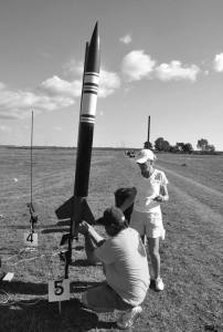
Another approach to stiff centering rings is to build them up from lightweight materials, much like an I-beam in skyscraper construction. For example, two flat rings become very stiff when separated with spacers. Centering rings like this are easy to build from materials like foam core, balsa, or thin plywood. They also have the advantage of greater surface area when glued into the airframe. You can even fill the void in the structure with a two-part expanding foam to add stiffness.
Given these options, there simply is no reason to slap heavy centering rings in a rocket. Remember, the lighter your rocket, the higher it flies on a given motor and the less robust your recovery needs to be for safe recovery.
Conclusion
There is simply no substitute for looking at the ways that other people build their rockets. Building stock kits is enjoyable, but after you complete a few of them, it is time to start modifying them for less weight, more airspeed, and greater durability. The tips and tricks above will keep you busy for a while, and by the time you’ve tried them, you will have seen enough variations that you’ll never run out of tricks to try on your next project.
Homemade Sanding Jig
Perfectly round bulkheads and centering rings for rockets can be made with the simple, homemade fixture. The fixture is clamped to the work table of a small inexpensive disk sander. Dimensions are not shown here, as they will vary with the size of the disk sander used. The drawing provides enough detail to build this fixture.
Make a 3/4-inch thick plywood lever with two 1/4-inch dia. holes located generally as shown. 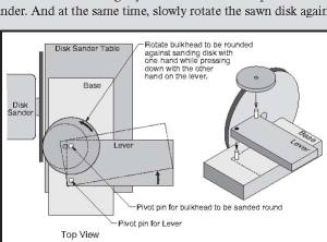 Make a 3/4-inch thick plywood base with one 1/4-inch dia. hole and glue a 1/4-inch dia. dowel rod with 3/4-inch extending up. Glue another 1/4-inch dia. dowel rod in the lever, also extending up. Mount the lever on the dowel rod protruding from the base.
To make a disk, use a compass to draw the disk diameter on a piece of thin plywood, such as 3/16-inch. Saw out the disk, being careful to saw outside the line drawn by with the compass. Slip the roughly sawn disk onto the dowel rod protruding from the lever. With the base securely clamped to your disk sander work table, slowly rotate the lever until the sawn disk engages the sanding disk. Hold the lever down tightly with one hand to keep it from moving in relation to the disk sander. And at the same time, slowly rotate the sawn disk against the spinning sandpaper disk until you have made a full revolution. Now, move the lever a little to remove more of the circumference of the disk, and continue the process. It works best to remove a little at a time and to stop after two or three passes to check the diameter of the disk with the tube into which it will be ultimately inserted.
Rocketry Paint and Finishing
Painting Your Model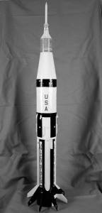
One thing that can really make your rockets stand out is a good paint job. Unfortunately, a good paint job is not that easy to accomplish. The really great paint jobs are the end result of a lot of preparation and the use of automotive paints and sprayers. But, with a little bit of effort, you can make your rockets stand out, even using spray paint purchased at the local hardware or department store.
Sanding and Priming
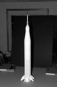 A large portion of finishing a model will involve sanding so make sure that you purchase some high quality sandpaper in a variety of grits for your project. It’s tempting to try to save money by using a cheap brand of sandpaper but in the long run that will cost you more in terms of time and money. In spite of what the name implies, modern, high quality, sandpaper does not actually use sand as an abrasive; instead they are coated with ceramic materials that cut better and don’t get clogged with debris as easily. Some cut-rate papers do actually use sand for an abrasive so they don’t last as long nor do they do as good of a job of smoothing a surface. Do yourself a big favor and spend a little bit more on your sandpaper – you’ll be glad you did.
To ensure that your rockets have a glass smooth paint finish you must ensure that the underlying surface is smooth. Start by using filler or spot putty to remove any dents, divots or wood grain and sand it smooth. What fillers and putties you use will depend on the materials you use to build your rockets. If you’re filling wood grain then I would recommend a good quality sanding sealer to get started. Apply several coats individually and sand between each coat. Properly used, sanding sealer will result in a perfectly smooth surface on your wood parts. I’ve also had good luck using light-weight wood filler on my wood fins and transitions. The wood fillers result in a smooth paintable surface with less work but the results are not quite as good as achieved with sanding sealer. For sealing other surfaces I normally use West Systems epoxy. This epoxy has a fairly long set time that allows it to self level. When filling holes I add micro-balloons to the epoxy to make a paste.
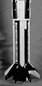 You will fill, prime and sand the surface several times while preparing for painting. After each pass, inspect the surface carefully looking for any imperfections that you may have missed. Repeat the process until the imperfections are removed. When you are satisfied that your rocket is completely free of surface imperfections (or when you feel it’s just good enough) then wipe the surface with a tack rag or a slightly dampened cloth to remove the sanding dust. When the surface is clean and dry apply a light coat of primer.
Allow the primer to dry, and then sand it off before you inspect the entire rocket, looking for problems. The primer will remain in any low areas on the surface of the rocket so you will be able to spot them easily. Minor imperfections will often be fixed as you apply and sand the successive coats of primer, but prominent dents and holes will require the application of filler, and bumps will need to be sanded smooth. Again, repeat these steps until you are happy that all of the surface blemishes have been removed to your satisfaction.
Once you are happy with how your rockets’ surfaces look, you’ll want to apply a final coat of primer. This coat is used to create a good surface for the paint to stick to and to provide a consistent base color so the paint can be applied evenly. I prefer to use a white sandable primer for this step but any color will work. Lightly sand this coat- you want to rough up the surface slight to ensure that the paint sticks – then remove the dust with a tack rag or damp cloth. You are now ready to apply the paint.
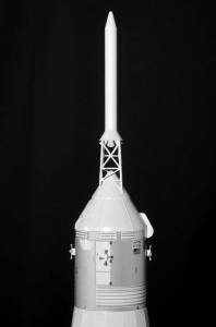 Applying Paint
You have some options when it comes to painting your model. You can paint the rocket using a brush but I certainly wouldn’t recommend that if you have spent any time priming it. You can use spray-paint cans which work fairly well and are reasonably inexpensive, but you will be limited to the premixed colors that are available from your local supplier. To get the best results, you need to use an airbrush or a paint sprayer, either one will allow you to use the highest-quality paint and mix the exact colors that you want.
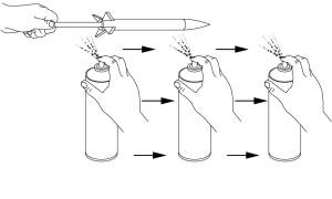
Regardless of the method you chose you will want to use good-quality paint and apply it in thin coats. Don’t try to get solid coverage with one pass; that will merely increase the chance of runs on the surface. If you are brushing the paint on, make sure you keep the brush wet with paint to avoid streaking. If you are spraying the paint, be sure to keep the spray nozzle approximately 6” from the surface of the model. The spraying distance is important; too close and the paint goes on too thick, too far away and you get small bumps as the paint starts to dry before contacting the surface you are painting.
It will take multiple coats of paint to get a good finish so make sure you have a good place to store the model while the paint dries. I prefer to wait for the paint to dry completely so I can lightly sand the surfaces between coats. However, some spray-paints allow additional coats to be applied before the surface has cured, so check the instructions for the paint you are using to see how long you must wait between coats.
 Adding More Colors
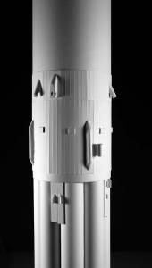
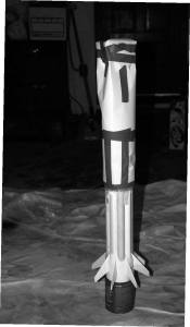
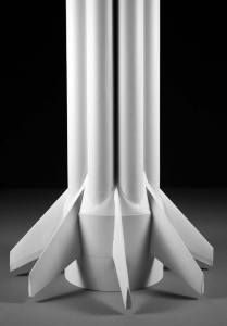
In the science fiction movies from the 1950s most of the rockets sported metallic silver surfaces and not much more. In reality rockets are normally painted in multiple colors. NASA frequently uses a base color of white with black roll patterns and other detail colors. Many modelers have found that their models look much better if they are given multi-color paint schemes. Applying additional colors can enhance the look of your models too.
Before adding additional colors make sure that the paint that has already been applied is completely dry. Handling your rocket before the paint has completely dried leads to permanent fingerprints on the surface. To spray additional colors you must first protect the areas that are already painted correctly. Do this by covering the areas that you don’t want to paint with masking tape or other materials. For example, if you have a large area to be protected you can use a combination of masking tape and paper to cover them. For very large areas plastic grocery or trash bags work very well.
After all the areas are masked it’s a good idea to make a final pass over the edges of the masking tape to ensure that it is pressed firmly against the surface of the model. Any gaps between the tape and the painted surface will allow the newly applied paint to seep under the tape, leaving you with a mess to correct – a very small gap can result in a very large mess. For best results, use a flexible rubber or soft plastic putty knife to press the tape edge into place. Avoid using a metal putty knife because they can easily scratch the paint surface. Repeat the masking and painting process for each additional color, making sure that each color has completely dried before masking the next one.
 The use of high quality masking tape can make a big difference when painting models. I normally use Tamiya paper masking tape that I purchase at the local hobby store. It is a very thin and flexible tape that was developed for hobby applications and is available in four different widths; 6, 10, 18 and 40 mm. If you cannot purchase Tamiya tape in your area then I recommend Scotch Blue Painter’s Tape for delicate surfaces. The Scotch tape is available in most hardware and department stores that also sell paint. It can be easily recognized because of the orange labeling inside the core. An automotive paint supply store would also have a good selection of masking materials.
If you spend a little extra time and use quality materials your rockets can become the ones that everyone is talking about.
Using West System Epoxy To Make Perfect Fillets
By Ed Dewey
I recently decided to try the West System pump epoxy system. I will not go back to using any thing else, especially squeeze bottles. West has many epoxies, but I chose the 105 Resin, Group Size A (32 oz.), and the 206 Hardener (slow), Group Size A.
You have to buy the correct pumps to go with these, and they screw into the cans in place of the lids (and they can stay there, pretty much until you want to use them again). The pumps work very precisely, dispensing the exact ratio of resin and hardener.
I found it easiest to squirt the amount I needed into a disposable plastic cup, mix it up, and apply the epoxy using an oral syringe obtainable at most pharmacies. This worked especially well on fillets. You just build “dams” at both ends of the fins with masking tape, lay in the amount of epoxy you want with the syringe, and let it set.
The 105-206 mix is not thick, and will level out very well. I use a small level on the rocket to make sure the fillets will be even from front to back. If you have any bubbles, just suck them out with the syringe.
The stuff hardens to a surface like glass and is easily filed, scraped, and sanded. West has a wide selection of additives, micro-fibers, and such, but I have not yet tried these. Others have and say they work very well.
Sanding and Sealing
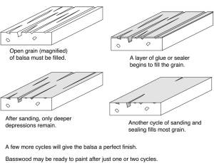 Open grain (magnified) of balsa must be filled. A layer of glue or sealer begins to fill the grain. After sanding, only deeper depressions remain. Another cycle of sanding and sealing fills most grain. A few more cycles will give the balsa a perfect finish. Basswood may be ready to paint after just one or two cycles.
Recovery
Types of Recovery Systems
By Carl Kruger
You have just watched your rocket shoot skyward, seeming to defy the law of gravity, but at the end of the rocket’s powered flight that same law will bring it streaking back to earth, coming in ballistic, unless you have provided a means to slow its descent—this is the recovery system. To insure the safety of persons and property, the NAR Safety Codes for model rockets and HPR require the use of positive recovery, a means to slow the rocket’s fall back to earth. Of course, in addition to safety, this also allows you to retrieve your rocket intact so it can be flown again.
Recovery Systems Types
Numerous types of recovery have been developed by rocketeers, some of which are described here.
Featherweight
Featherweight recovery can be used on a very small, light rocket. At apogee the spent engine casing is ejected from the model. The model then flutters to the ground like a feather. Unfortunately, the engine casing is also subject to the law of gravity and therefore, being comparatively dense, will fall to earth more rapidly. This is not a problem if you don’t happen to be standing under it when it lands.
Tumble
Similar to featherweight recovery, except that the engine casing is not ejected, this method is commonly employed on the booster stages of multistage designs. The large fin area makes for an acceptably slow rate of descent, if the booster stage is not so stable that it comes in pointed down, fast.
Streamer
 A streamer is simply a flat strip of material (plastic or crepe paper) that provides wind resistance to slow the rocket’s descent. A streamer is well suited to a lighter airframe, particularly one that is expected to attain high altitudes, where a parachute would let the rocket drift excessively. The streamer size must be appropriate for the airframe size.
 Parachute
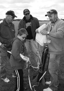
This is the most commonly used means of recovery. Most rocket kits include a parachute or, more accurately, a “parasheet.” Normally made of a thin sheet of plastic film (like a trash bag) to which several (normally six) shroud lines are attached, forming a canopy. Attached to your rocket airframe, the canopy fills with air and slows the rocket’s descent.
The parachute must be sized appropriately to match the size of your rocket. Too small a ’chute will not slow the rocket’s descent sufficiently to prevent damage, while too large a ’chute may not open fully or may carry the rocket far from the launch area. The right-sized ’chute will deploy fully with your rocket swinging gently below it, for a gentle landing near the launch area with no damage to the rocket, people, or property.
Glider
Many variations of this type of recovery have been developed over the years. Some simply mate a glider with an engine pod that detaches at apogee and return s via streamer or parachute while the glider part of the airframe glides to earth. Some deploy wings at apogee and glide to touchdown. The secret here is to make a model that is stable in both vertical and horizontal flight paths.
Recovery-Device Deployment
The most common method of model-rocket recovery-device deployment utilizes the engine’s ejection charge (refer to motor article) to alter the state of the airframe (e.g., pop the nosecone, eject the engine, disengage the engine pod, etc.).
Electronics can also trigger a small BP charge to deploy the recovery device. The electronics may be a timer, altimeter, or radio control (RC) device. These are most commonly used in mid and high-power designs. High-power rockets sometimes use a dual recovery system. A small drogue parachute is deployed at apogee, slowing the rocket in the initial phase of recovery, but not so much that the rocket drifts out of sight. Then, in the final stage of recovery, a larger parachute, deployed at lower altitude, slows the rocket even more, so that it lands gently.
In any case, you must protect your recovery device from the hot gases of the ejection charge. This can be accomplished with recovery wadding, available from most engine manufacturers. Although some of this material looks like tissue paper, it is treated with a flame retardant. Toilet paper, newspaper and similar materials are not appropriate for recovery wadding; the hot ejection gases would ignite the paper as the rocket separates; some of the burning paper could reach the ground and start fires. Cellulose insulation can be used, however, as it has been treated with a flame retardant. Nomex ’chute protectors are also a good supplement to recovery; Nomex is essentially Kevlar in cloth form.
Tips for Successful Deployment
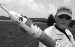
• Whatever ’chute protection you decide to use, don’t pack it tightly in the body tube, or the charge may not be sufficient to eject it.
• Before folding your parachute or streamer, give it a light dusting of talcum powder. This helps keep the plastic film from sticking to itself and increases the chances for full deployment.
• Fold your parachute or streamer neatly, and wrap the shroud lines around it so that it slides freely into and, more important, out of the body tube.
• A rocket flight simulation program is helpful in estimating the appropriate time or altitude at which to set your timer or altimeter events when using electronic deployment.
Additional Topics Covered in the hardcopy Members Guidebook you’ll receive for Joining the NAR.
SCT-1: Mexico’s Baby V-2 . . . . . . . . . . . . . . . . . . . . . . . . . . . . . . . . . 16
What Is Team America Rocketry Challenge? . . . . . . . . . . . . . . . . . 19
Rocket Stability . . . . . . . . . . . . . . . . . . . . . . . . . . . . . . . . . . . . . . . . 20
Rocket Performance . . . . . . . . . . . . . . . . . . . . . . . . . . . . . . . . . . . . 22
Rocket Design Software . . . . . . . . . . . . . . . . . . . . . . . . . . . . . . . . . .25
What’s in a Rocket Motor? . . . . . . . . . . . . . . . . . . . . . . . . . . . . . . . .28
Multi-Stage Rocketry . . . . . . . . . . . . . . . . . . . . . . . . . . . . . . . . . . . 30
Cluster Rocketry . . . . . . . . . . . . . . . . . . . . . . . . . . . . . . . . . . . . . . . 34
Launch Systems . . . . . . . . . . . . . . . . . . . . . . . . . . . . . . . . . . . . . . . 36
High Power Rocketry Certification . . . . . . . . . . . . . . . . . . . . . . . . 38
NAR Educational Awards . . . . . . . . . . . . . . . . . . . . . . . . . . . . . . . 42
Modular Design . . . . . . . . . . . . . . . . . . . . . . . . . . . . . . . . . . . . . . . 43
Estes Modeling Secrets . . . . . . . . . . . . . . . . . . . . . . . . . . . . . . . . . . 46
A Simple Rocket . . . . . . . . . . . . . . . . . . . . . . . . . . . . . . . . . . . . . . . 49
Section Benefits . . . . . . . . . . . . . . . . . . . . . . . . . . . . . . . . . . . . . . . 52
NARTS Catalog. . . . . . . . . . . . . . . . . . . . . . . . . . . . . . . . . . . . . . . . .54
What Is NARTREK? . . . . . . . . . . . . . . . . . . . . . . . . . . . . . . . . . . . 56
Questions about NAR Insurance . . . . . . . . . . . . . . . . . . . . . . . . . . 58
Rocket Safety. . . . . . . . . . . . . . . . . . . . . . . . . . . . . . . . . . . . . . . . . . 60
Member Services . . . . . . . . . . . . . . . . . . . . . . . . . . . . . . . . . . . . . . 63
© 2010-2015, National Association of Rocketry. All rights reserved. No part of this publication may be reproduced or copied in any form or by any means, graphic, electronic or mechanical, including photocopying, recording, taping or via information storage and retrieval systems without prior written permission of the National Association of Rocketry. The NAR would like to thank the following people for making this guidebook possible: Mark Newton, Mario Purdue, Ed Dewey, Carl Kruger, Peter Alway, Trip Barber, Rick Weber, Tim Van Milligan, Greg May, Drake “Doc” Damerau, Jim Wilkerson, Stew McNabb, Joyce Guzik, Riccardo Paleari, Cristiano Casonati, Mike Dorffler, Ken Jarosch, Art Upton, and Ted Cochran.